Polar Instruments Ltd, United Kingdom


Polar UK: ATLAS - PCB Insertion Loss measurement system

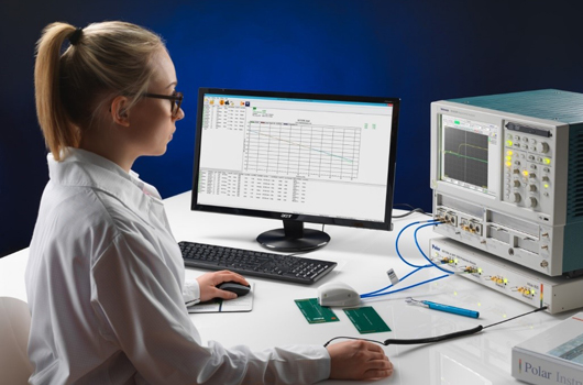
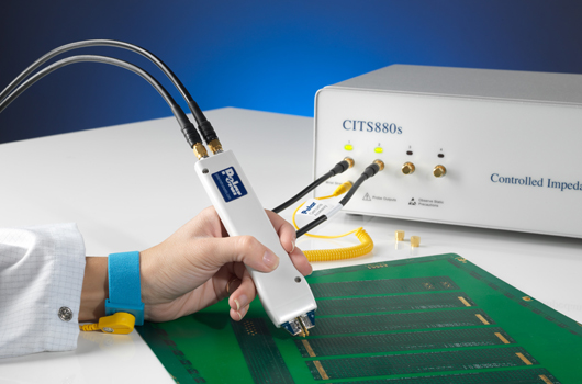
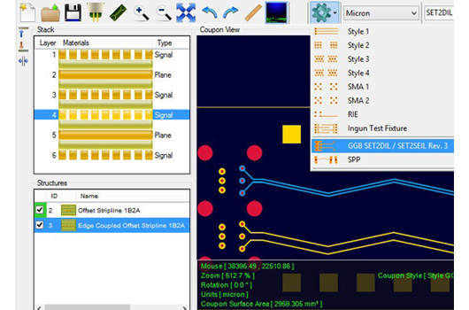
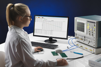
ATtenuation Loss Analysis System is new test solution for PCB fabricators to test PCB transmission line insertion losses in a tightly controlled production environment. ATLAS 2013 now includes a dedicated intelligent ESD protection unit, new ergonomic probe housing and updated version 13.04 sofware with a raft of new feature enhancements. ATLAS 13.04 software interfaces with industry standard Tektronix DSA8300 oscilloscope TDRs and supports INTEL developed SET2DIL (Single Ended TDR to Differential Insertion Loss) and SET2SEIL (Single ended TDR to Single Ended Insertion Loss) test methodology for extraction of differential insertion loss from a single ended test and suitably designed coupon. Atlas 2013 is compatible and upgradeable to IBM developed SPP (Short Pulse Propagation) test methodology which will be released soon. Also available as ATLAS PCB for performing industry standard CITS style controlled impedance testing using Tektronix TDRs.

System configurations:

ATLAS - Atlas Software with HF Probes and Loss Test Standard
Download Brochure
C Gen Plus—Auto Coupon Generator for SET2DIL Lossy Coupons. 
Download Brochure

Polar UK: Si9000e PCB transmission line modeling

With its fast, accurate, frequency-dependent transmission line modeling, the Si9000e is designed to model transmission line loss, impedance at given frequencies and extract full transmission line parameters over a wide range of popular PCB transmission lines (over 100 structures). The Si9000e extracts RLGC matrices and rapidly plots a range of transmission line information for the structure you are designing. Loss is graphed three ways with clear indication of dielectric, copper and total loss and from 2017 includes Hammerstad, Groisse and Huray methods for roughness modeling.

Main Features

  • Links with Speedstack as Speedstack Si
  • Si Crosstalk option – Multi line and differential pair (lossless) crosstalk – models coupling between traces
  • Si Projects option with Speedstack saves structure groups
  • Roughness modeling – Smooth / Hammerstad / Groisse / Cannonball-Huray
  • Inbuilt impedance graphing
  • Graphs conductor, dielectric and insertion loss
  • At-a-glance comprehensive S-parameter charting – magnitude, phase and Smith charts
  • Single-ended and Mixed-mode S-parameters charting and data tables
  • User defined S-parameter source and termination impedance
  • Frequency dependent modeling down to 1KHz
  • Go / no go via stub check

Si9000e options 

  • XFE option – provides crosshatch return path modelling for flex and flex-rigid PCBs 
  • Si Crosstalk option – Multi line and differential pair (lossless) crosstalk – models coupling between traces 
  • Si Excel Interface option – Microsoft Excel® interface option for lossless calculations in Si9000e 
  • Si Projects option with Speedstack Si saves structure groups 

Download Si9000e Brochure


Polar UK: Atlas Si – PCB insertion loss testing for PCB fabricators and Si engineers

Polar Atlas software enables PCB fabricators to test PCB transmission line losses in a tightly controlled production environment. Atlas employs mathematical processing techniques* to extract frequency dependent loss characteristics when used in conjunction with suitably designed test coupons and Atlas precision GHz probe assemblies.

Atlas packages interface either with industry standard Tektronix DSA8300 or DSA8200 oscilloscope TDRs. Fabricators can choose to add Atlas to their existing Tek DSA or alternatively Polar can supply a turnkey package.

Atlas supports multiple test methods including Delta-L, Delta-L 3 Line, SET2DIL (Single-Ended TDR to Differential Insertion Loss) for extraction of differential insertion loss and effective Er from a single ended test and suitably designed coupon, SET2SEIL method (Single-Ended TDR to Single-Ended Insertion Loss) for single ended insertion loss testing and SPP (Short Pulse Propagation) methods as called for in IPC-TM-650

Main Features

  • Atlas software is designed to assist PCB fabricators in the accurate and repeatable measurement of PCB transmission line losses in a PCB production environment.
  • Ergonomic probe housing:
  •  Tracks system risetime and monitors the system bandwidth.
  • Delta-L - Atlas supports the Delta-L technique (v16_04 fully incorporates rev2p31 of Delta-L with the current settings and parameters) which uses long-line short-line measurement combined with innovative via de-embedding techniques, Delta-L provides a sound method for removing the via effects from differential (mixed mode) s-parameters when characterizing raw PCBs for insertion loss.
  • SET2DIL/SET2SEIL - Atlas test methods also include both the SET2DIL (Single-Ended TDR to Differential Insertion Loss) and SET2SEIL (Single-Ended TDR to Single-Ended Insertion Loss) test methods for extracting differential insertion loss from single ended measurements.
  • SPP – Short Pulse Propagation  - SPP allows extraction of PCB electrical characteristics that impact signal propagation; it uses your existing TDR/TDT equipment and produces frequency dependent parameters such as the propagation constant (alpha, attenuation and beta, phase constant) and effective dielectric constant along with the characteristic impedance (including even and odd mode impedance.) Atlas measurements include launch point extrapolation/long line regression fit.
  • Controlled impedance test - Atlas GHz test software is also capable of traditional lossless controlled impedance test

Download Brochure

Polar UK: Si8000m Lossless PCB Controlled Impedance Field Solver

The Si8000m is a boundary element method field solver that builds on the familiar easy to use user interface in earlier Polar impedance design systems. The Si8000m adds enhanced modelling to predict the finished impedance of multiple dielectric PCB builds and takes into account the local variations in dielectric constant on close spaced differential structures. The Si8000m assumes negligible insertion loss in the transmission line. The Si8000m field solving impedance design system offers advanced field solving methods to model most circuit designs and is totally complementary to the CITS880s and RITS550/880 manual and automatic Controlled Impedance Test Systems.

Main Features

  • Powerful impedance design system
  • Impedance Goal seeking
  • Model multiple dielectric PCBs
  • 16 Single ended structures
  • 27 Differential structures
  • 36 Single ended coplanar structures
  • 36 Differential coplanar structures
  • Reduce time to market
  • Graph production variations
  • Single ended and differential modelling
  • Calculate the effect of resin rich areas
  • Enhanced soldermask models
  • Optional track resistance calculator

Si8000m options

  • XFE option – provides crosshatch return path modelling for flex and flex-rigid PCBs
  • Si Crosstalk option – Multi line and differential pair (lossless) crosstalk – models coupling between traces
  • Si Excel Interface option – Microsoft Excel® interface option for lossless calculations in Si8000m/Si9000e
  • Projects option with Speedstack saves structure groups

Download Si8000m Brochure

Polar UK: Toneohm T-950 Shorts Locator

Polar's world famousToneohm 950 helps to identify different types of shorts on a loaded / bare circuit boards. It’s unique Vector Plane Stimulus (VPS) technique enables to identify plane to plane or track to plane shorts in quick time. Toneohm 950 is widely used in the PCB repair, troubleshooting and manufacturing industry for short location. 

Download Brochure

Polar UK: CITS880s - Controlled Impedance Test System

CITS880s system is the 9th generation impedance test system from Polar Instruments Ltd, UK. It is a solution for fabricators who need to measure impedance on fine traces and thin copper. CITS880s features Launch Point Extrapolation (LPE) that extrapolates the TDR response to a point close to the start of the transmission line effectively aloowing users to measure the instantaneous or incident impedance of the line more acccurately.

In addition to the LPE the CITS880s is also capable of measuring shorter traces - typically 2-3 inches shorter than previous generation of the CITS series. CITS880s now ships with completely re-engineered IPS and IPDS high speed probes whcih reassuringly are precision moulded with ESD dissipative materials to give maximum protection to your CITS.

Polar IPS and IPDS high speed probes are specifically desgined for CITS880s. They combine revised internals with more robust mechanical design and enhancements to the signal path, along with ergonomic precision mouldings in 100% ESD dissipative materials. IPS and IPDS probes are easily identified and contrast with previous generation probes by the use of the blue labels and blue resists on the probe tip interface.

Click here to see what's new in the CITS880s.

Polar UK: Speedstack Si – Stackup design for impedance & insertion loss controlled PCBs

Speedstack Si insertion loss controlled PCB stackup design tool is made for a designer, fabricator or PCB technologist who needs to manage PCB stackups with both impedance and insertion loss control. In addition to incorporating insertion loss field solver capability, Speedstack Si allows rapid import and export of insertion loss projects into the Si9000e insertion loss field solver so you can analyze the stack up design in detail.

Speedstack Si delivers rich reporting capability and not only generates the stackup material data but also graphs predicted insertion loss characteristics – including industry standard modeling for roughness using Hammerstad, Groisse and Cannonball-Huray methods.

Download Speedstack Si Brochure

Polar UK: Speedstack PCB – PCB stackup / Impedance field solver package

Speedstack PCB stackup design tool is a packaged combination of the Si8000m field solving impedance calculator and the Speedstack professional layer PCB stackup design system. It allows both impedance calculation and layer stackup/build up documentation.

For PCB fabricators, Speedstack PCB interfaces with the industry standard Polar Si8000m PCB Controlled Impedance Field Solver. It includes a link and license for Polar’s Si8000m, using the proven Polar Si8000m multiple dielectric boundary element field solver to provide the impedance data for the stack.

Ideal for both rigid and flex-rigid stackups

Speedstack PCB allows OEM designers to create accurate and efficient rigid and flex-rigid PCB stackups in just a few minutes, with error-free documentation for tighter control over the finished board. For PCB fabricators, Speedstack PCB provides the flexibility to quickly calculate the impact of substituting alternative materials to improve manufacturability and reduce cost while maintaining the specified parameters and performance of the board. The Navigator provides a clear contextual view of the rigid and flexible stacks within a flex-rigid build and allows easy alignment of displayed materials between stacks.

Speedstack PCB can be used when modelling and documenting mesh/crosshatch ground. Structure data and mesh geometry can be readily shared between Speedstack and the field solver. The associated technical report also supports different materials on the same dielectric layer, improving the clarity of documentation between the stackup designer and fabricator.

Download Speedstack PCB Brochure

Polar UK: Speedstack Flex – flex-rigid PCB stackup design and documentation tool

Speedstack Flex flex-rigid PCB stackup design tool allows PCB fabricators and OEM engineers to create and document flex-rigid PCB layer stackups using the Speedstack family of PCB stackup design tools.

It allows OEM designers to create an accurate and efficient flex-rigid PCB stackup in minutes, with error-free documentation for tighter control over the finished board. On the other hand, for PCB fabricators, Speedstack Flex provides the flexibility to quickly calculate the possible impact of substituting alternative materials to improve manufacturability and reduce cost while maintaining the specified parameters and performance of the board.

 Main Features

  • Mesh / Crosshatch ground planes
  • Internal Coverlays
  • Doublets - provides for situations where two or more flexi cores are present with an air gap in between.
  • Definable colours per material
  • Powerful stack browser / search option
  • High quality error-free documentation

XFE Cross Hatch Flex Enhancement

Polar has produced an alternative approach to modeling crosshatch using a proprietary technique, XFE (Crosshatch Flex Enhancement) this technique uses Polar's 2-D field solvers but uses a unique algorithm to correct for the effects of flex over a wide range of typical controlled impedance structures.

This approach has enabled solvers to model more closely the effects of a wide variety of crosshatch geometries. The XFE option, applicable to both Polar’s Si8000 lossless transmission line impedance solver and to the lossless mode of the Si9000 frequency dependent, lossy transmission line field solvers allows for configuration of hatch pitch (HP) and width (HW) as shown in the above graphic

Main Benefits of XFE

  • Reduces prototype turns when producing impedance controlled flex PCB
  • Provides modeling for controlled impedance lines with crosshatch or mesh ground returns
  • Modeling is based on proven Polar BEM solver
  • Available as an option for Si8000m and Si9000e for all lossless transmission lines
  • Useful for any PCB type deploying meshed / crosshatched return planes e.g. interposers

    Polar UK: CGen PCB / CGen Si - PCB impedance and insertion loss coupon generators

    CGen Coupon Generator reduces the time-consuming process of creating impedance coupons manually to just a few minutes, adding powerful new features that give coupon generation new levels of control and flexibility.
    CGen PCB Coupon Generator is an automatic impedance coupon generator that allows you to create a controlled impedance test coupon from scratch or import finished stacks from Speedstack PCB and Speedstack Si or structures from the Polar Si8000 and Si9000 field solvers.

    CGen Si incorporates all the features of CGen PCB and adds insertion loss coupon capability. Please note designs for insertion loss coupons need to be fine-tuned to OEM requirements and final adjustment of launch and via structures may still be required. If in any doubt – please check with your design authority.

    Replacing scripted coupon generation

    CGen replaces time consuming manual or scripted coupon creation with a simple four-stage process:

    • Import or create coupon layer stackup and impedance structure
    • Select coupon and impedance test probe
    • Edit and preview changes in real-time
    • Export Gerber and drill files

    Download Brochure